A few weeks ago I stumbled upon a paper by Huang et al., which described a certain type of digital camera, which only has a single sensor, no lenses and takes several minutes to take blurry pictures.
I have talked about why this is still interesting, but not particular useful in an earlier post. One can buy digital cameras for very little money that are superior in any respect.
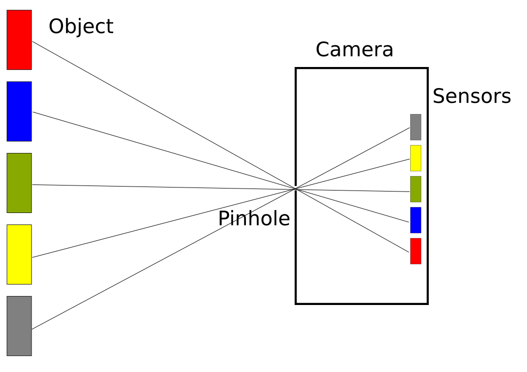
Usual cameras have a single aperture, in the simplest case a small pinhole. Light entering the camera has to go through this pinhole, and these rays form a inverted image of an object on the backplane. One can then put many light sensors on the backplane and measure the intensity of the light, and from this obtain a digital image.
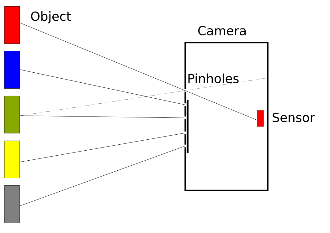
This other design (I will call it inverted camera) somehow turns this idea around. It uses many pinholes (also called aperture assembly) and only one sensor. The pinholes can be opened and closed individually. To get one pixel of the image, one has to close all but one of the pinholes.
This design makes it necessary to take the measurements for the light intensity of different pixels one after the other, whereas in the non-inverted design all pixels can be measured at once in parallel. The time required to make a picture is therefore much longer in the inverted design. But it also has a few advantages:
- super simple
- only one sensor is needed
- no lenses required
For the application of compressed sensing this setup is cool, because it allows to take measurements of several pixels at once, which is one of the requirements. The result is, that one can cut the total number of measurements by a factor of 5 or more, and reduce the total time it takes to record a image.
The plan
But its simplicity also allows to actually build a inverted digital camera, without having to deal with CCD sensor arrays or other complicated electronics. So I decided to try that.
A while ago I got me an Fritzing StarterKit, which contained most of the required components, in particular a light dependent resistor, which can be used as a sensor.
Huang et al. have used a LCD display without background illumination. Switching a pixel from black to white corresponds to opening a pinhole. With this setup they achieve a relatively large resolution and can switch pretty quickly.
But I do not have a LCD display, so I decided to realize the pinhole switching by a stripe of transparent material with a printed pattern. Black corresponds to a closed pinhole, because the black ink blocks most of the light, whereas white corresponds to a open pinhole, as the stripe is transparent. This is a bit like with analog movies in the cinema, but inverted.
To keep track of which pattern is currently active, I planned to use a optical fork sensor and a control pattern on the side. The stripes is easy to produce on a printer, but the actual measurements are much slower, than with a LCD, because one has to pull the stripes manually. Even with the most sophisticated reconstruction algorithms one needs to do one measurement per 20 pixels, so megapixelphotography is certainly not possible with this approach.
The camera body
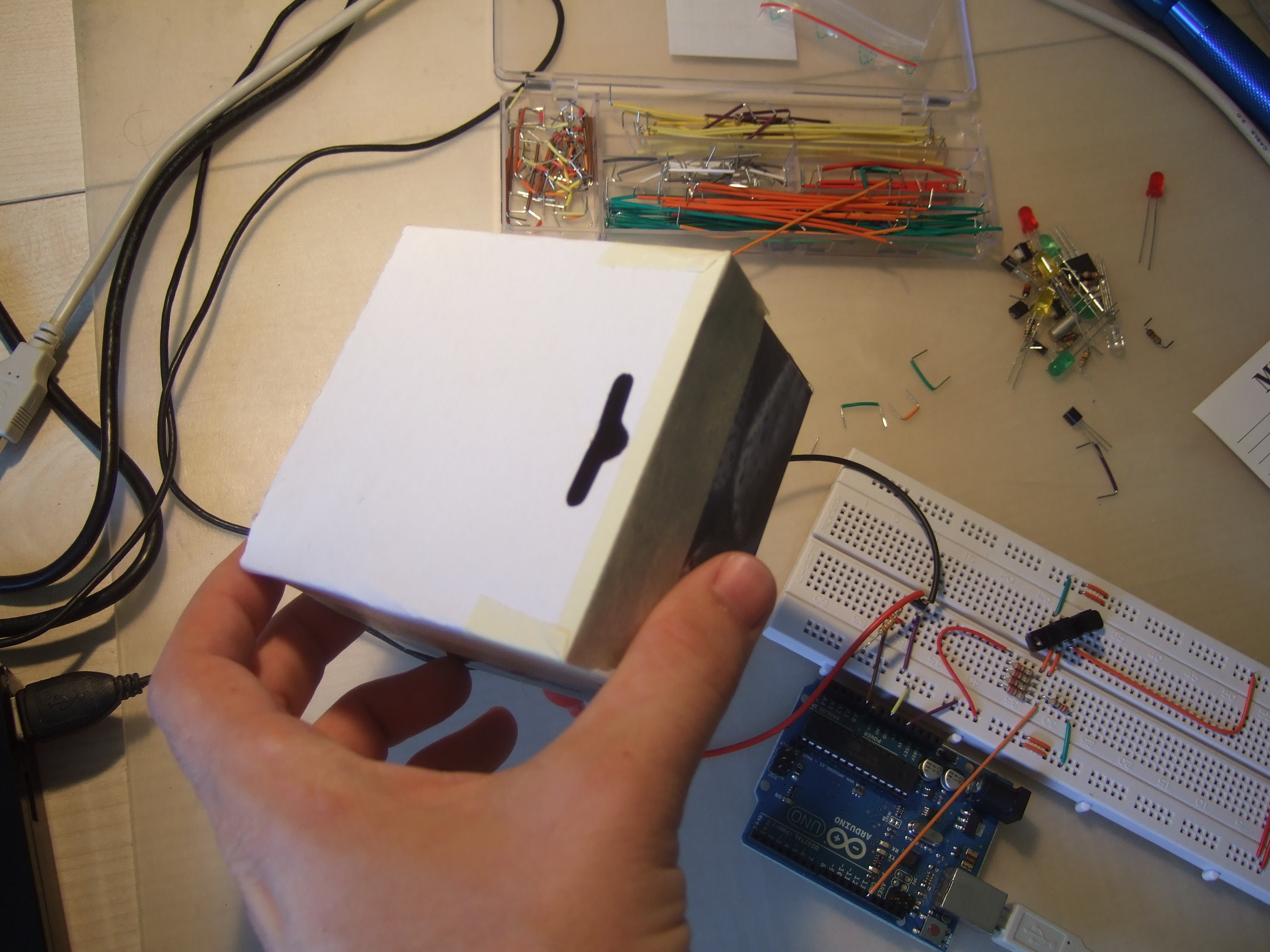
The first thing I did was to try to read the photoresistor with my arduino and to check whether there is a chance to detect small enough changes of light. I used a small box with a hole in it, in which I mounted the LDR. And it worked, I got readings that changed a lot depending on the direction of the hole.
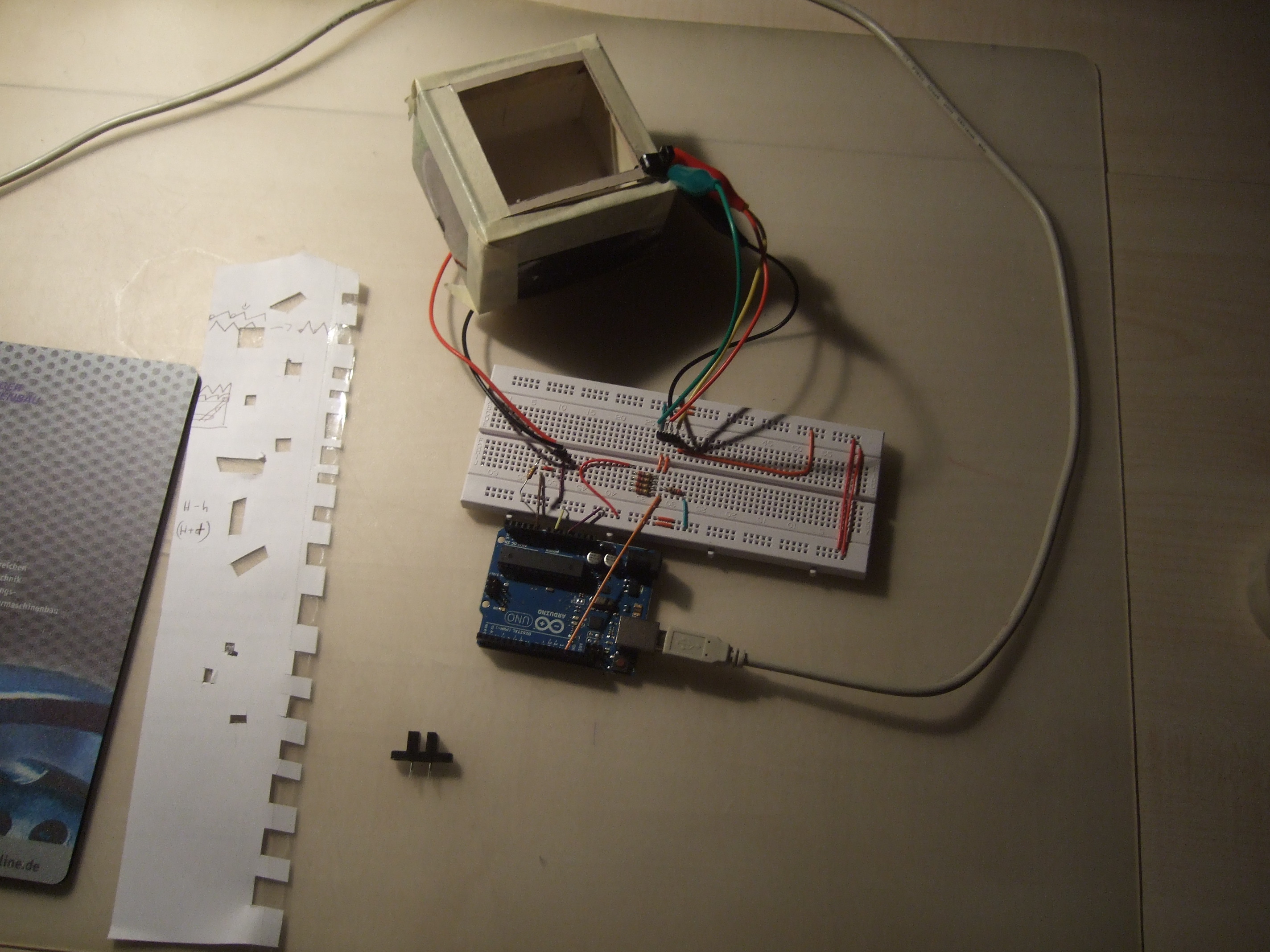
I tried to whip up an aperture assembly using card board again, but that did not work at all. The plan is to have guides, that keep the transparent stripe in place and align the control pattern properly for the optical sensor. But cardboard was just to fragile. In the picture one can see the cardboard version, with the optical fork sensor in the lower right corner, attached with my croco-clip-to breadboard adapter. On the left is a mockup of the stripe with the control pattern on the right. Below the arduino is another optical fork sensor to illustrate its geometry. It gives a signal that tells whether the space between the two prongs is blocked by something intransparent.
Together with my father I designed a better version that I could print on my 3D printer. It worked very well on the first try, but I have no close up pictures of it. I mounted it on my trusty cardboard box with lots of tape. In the long run, I plan to design a completely printable body, where everything is mounted properly.
The circuit
I do not know very much about electronics, but luckily, that was not necessary. The circuit only needs to read out the light dependent resistor, and for that a simple voltage divider wired up to one of the analog inputs is sufficient. Then the optical fork sensor needs to be hooked up to the arduino, but this is described in the data sheet, and requires only two resistors.
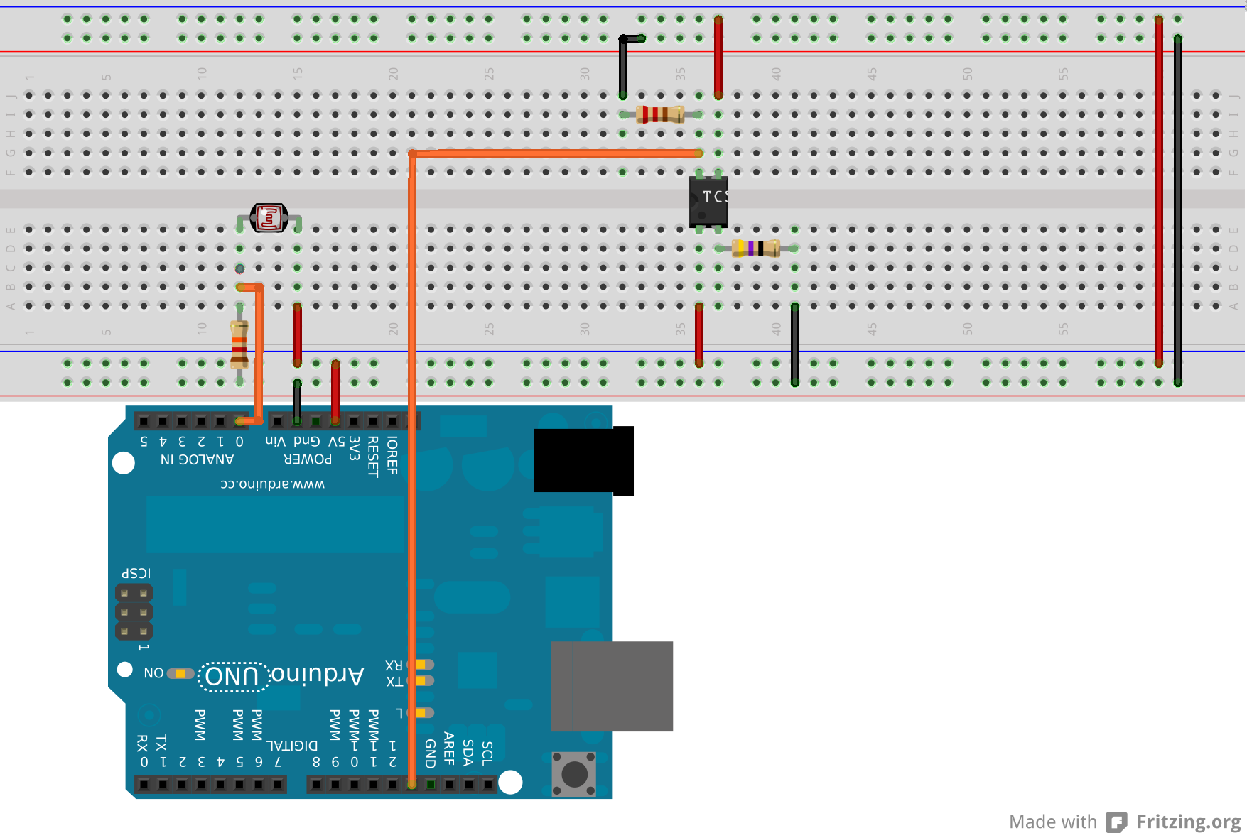
I drew it up in Fritzing, and then built it on a breadboard. It is a bit bulky and very prototypey, as can be seen from the picture above. Some day I might (or might not) design a proper arduino shield and sent it to the Fritzing Fab.
The bill of materials for this first circuit is very short, and the cost (excluding the Arduino) are below 5 Euro:
| Amount | Part |
|---|---|
| 1 | Optical fork sensor TCST2103 |
| 1 | 47 Ohm Resistor |
| 1 | 220 Ohm Resistor |
| 1 | 12 kOhm Resistor |
| 1 | 10-200 kOhm LDR |
| 1 | Arduino Uno |
Maybe I will also experiment a bit with amplification of the signal and LEDs as sensors. I have a multi color LED, I wonder whether this can work as a color sensor. There are also 3 color LDRs available for about 1 Euro, which would allow color pictures
The software
For the software part there are really four components: The arduino firmware, something that talks to the arduino to get the measurements, the reconstruction algorithm and a bit of code to create the pattern stripes.
The arduino firmware is basically a combination of the examples for analog reading, digital reading and serial port communication and is more or less trivial. It just checks, whether the fork sensor signal has changed from unblocked to blocked, and if this is the case, it reads out the LDR and writes the result to the serial port.
One of the motivations of this project was to play around with compressive sensing and interesting reconstruction algorithms. However, I did not get it to work, either there is a problem with my reconstruction algorithms or with my hardware, or probably both. I got much better results in "scanning mode", where only one pinhole is open at a time and one pixel value gets measured at a time. For this mode, reconstruction is trivial.
To create the patterns, I whipped up a bit of python code, that produces svg files with the patterns. They are constructed according to a number of parameters, like the size of the paper, the width of the guides, the dimensions of the pattern and the resolution.
It tries to overlap patterns that are partly the same. This is especially important in scanning mode, as the patterns there are almost completely black. With the right ordering, one can overlap almost all patterns, saving a lot of space. For example, without overlapping 4 patterns fit on a stripe of the length of a A4 page with resolution 6x6 pixels, with overlapping its 19 patterns.

The results
As mentioned earlier, I could not get compressive sensing to work, but only scanning mode. I setup a simple scene, that would be easily recognizable as success or failure, even at the resolution of 6x6 pixels that I used.
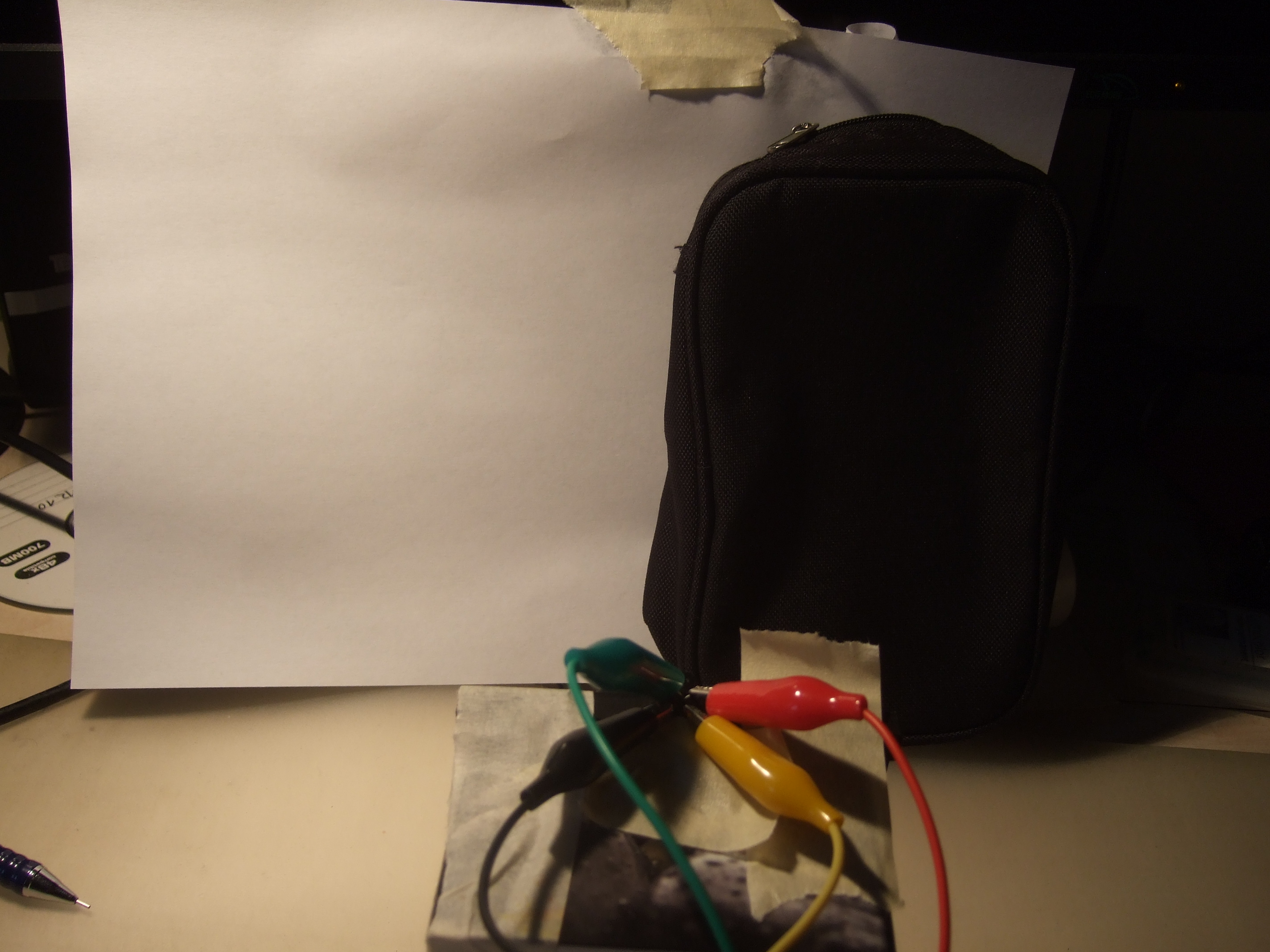
I then took 36 measurements, using the two stripes shown above. The resulting image is the following:
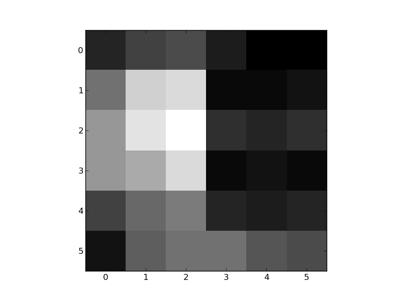
I count this as a success. The black bag is clearly visible, but everything is relatively noisy. But on the other hand I consider it a success to obtain such a result using such a simplistic setup. There is clearly a lot of opportunity for improvement.