When designing 3D printers, Bowden extruders offer one very significant advantage: There is no need to place the heavy motor of the filament drive on the carriage. This reduces the mass of the moving parts significantly and allows for faster movement of the carriage. On the other hand, the Bowden mechanism also has disadvantages: Increased friction and increased hysterisis due to filament and tube springiness.
A while ago I was thinking about an idea that also allows to remove the motor from the carriage, but keeps the actual driving mechanism (hobbed bolt or similar) there. But without a motor on the carriage how is the power transmitted to drive the filament?
One axis leadscrew mechanism
My first idea was to use the 2 lead screws: The carriage is driven by a nut attached to one of the lead screws. A gear is placed between them, attached to the hobbed bolt and is driven by the differential motion. If both screws turn into the same direction, the gear acts as an additional nut (actually, the nut can be omitted) and the carriage moves, but doesn't rotate. If both screws turn into opposite directions, the gear turns, driving the filament into the hot end. An arbitrary combination of feed and carriage movement can be achieved by choosing appropriate turn rates for the two screws. For example, if only one of the screws is turned, the gear and the other screw basically form a rack and pinion and move and turn with half the rate.
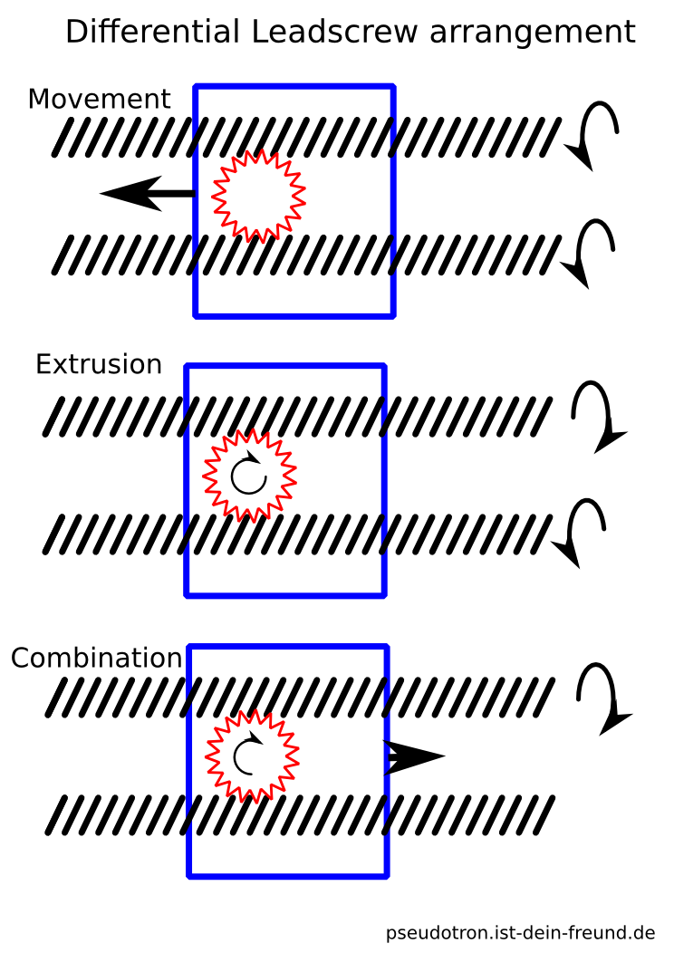
This would allow to move the motors away from the carriage. Depending on the layout of the axes they are either located on a slow axis (i.e. z in a Mendel configuration) or completely stationary (in a Orca layout). The carriage itself could be designed very compact when the gear is directly attached to the hobbed bolt and the two lead screws are arranged vertically.
However, proper lead screws are relatively expensive, and i am not sure if gears with the necessary tooth profile are available. One would also need to estimate the necessary feed and flow rates to check whether one can get away with directly driving the extruder or if it is necessary to gear it down.
One axis belt mechanism
An alternative (and cheaper) idea came to me when I read Richraps Sli3DR announcement <http://richrap.blogspot.de/2014/11/sli3dr-3d-printer-design-files-up-on.html>, and noticed the neat cable drive mechanism, which allows to have the motors stationary. Instead of driving the extruder by the differential motion of lead screws, one could achieve a similar effect using belts, with a few modifications of the drive mechanism. For one axis the belt driven equivalent to the lead screw mechanism above looks like this:

One needs a closed, belt, preferably with teeth on both sides. The filament drive is attached to one of the pulleys on the carriage. This belt is driven by two motors (marked green). By driving the motors equally in opposite directions, only the carriage is moved, by driving the motors equally in the same direction, the pulleys on the carriage are rotated, and again every combination of movement and filament feed can be achieved by choosing appropriate rates for the motors. Again it seems like this could be neatly realized in combination with vertically arranged smooth rods.
Two axis belt mechanism
This concept can also be generalized to a 2 axis mechanism, which could for example be used in a Sli3DR (or Ultimaker) configuration of axes. In this case 4 stationary motors can drive the carriage in two directions and drive two filament drives independently, which allows for dualstrusion or colormixing:
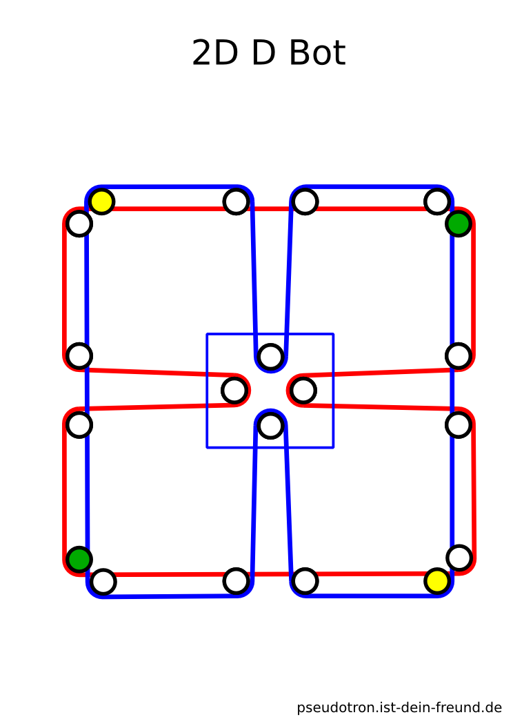
The nice thing about this mechanism is that it degrades gracefuly, i.e. if one only wants to 1 filament drive, one of the motors (yellow and green here) can be replaced by a clamp that fixes the belt.
A complication that is shared by all these ideas is that it requires changes to the firmware, as the axes are not independent anymore, but two (in the case of the 1 axis mechanisms) or four (for the 2d arrangement) motors need to be driven to move one of the two (X,E) or four axis (X,Y,E1,E2). On the other hand, delta printers require the same, but with kinematics that are much more complicated.
I term these arrangements D Bots, as they are very similar in spirit to the H Bot mechanism. The D stands for differential, as it uses the differential motion of elements to drive the filament. The CoreXY page presents another related mechanism and lists some references.